1. Introduction
A chamber room in this experiment is known as an automation circuit. It’s designed to keep the room temperature at a certain degree. This chamber room is chosen as one of the training for automation.
Here we learned how to design our concept using ladder logic, and then realize the physical circuit by using a few automation devices. The purpose of this training is to introduce to few automation devices which are relay, contractor and thermal couple. We built an experimental chamber room based on the ladder diagram we designed.
Here we learned how to design our concept using ladder logic, and then realize the physical circuit by using a few automation devices. The purpose of this training is to introduce to few automation devices which are relay, contractor and thermal couple. We built an experimental chamber room based on the ladder diagram we designed.
2. Experiment Design
The chamber room how we wanted to work here is by using a heater to heat a room, when the room temperature is lower than the set temperature (cooler) the heater will be on to heat the room, but if it is higher (hotter) the heater will turn off. The heater will turn on again when the temperature drops.
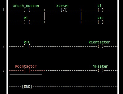
Figure 1. Ladder diagram of chamber room
Figure 1 shows the ladder diagram of chamber room we wanted to make. The concept is locking the room temperature.
a. When the button is pushed an electric current will flow to relay R1 (pin 13 to 14) and activate thermocouple (RTC) while R1 (pin 9 to 5) will lock the current even if the push button is off (the light will remain on). The left side is the positive node connected to the power supply while the right side connects to the ground. The numbers on Figure 1 are pins which will be explain later on.
b. The thermocouple will activate the Contractor and activates the heater.
c. The thermocouple will sense the room temperature and when it reaches the set temperature (heats), the thermocouple will switch off (cut the line).
d. Electric current will stop flowing to contractor hence shutting down the heater.
e. After a while the room temperature will drop (cools down) and again activating the thermocouple (let current flow) and activates the contractor with the heater.
f. The cycle will go on locking the room temperature.
The relay (R1) is set to lock the flow of electric current to the thermocouple since we’re using a push button. Without it the circuit will turn off after we release the push button while we want it to keep turned on even if we release the push button.
For the ladder diagram above we use a push button, reset button, relay, thermocouple, contractor, and light bulb as an indicator while we use a solder to heat the heat sensor on the thermocouple. Figure 2 shows a relay:
a. as in Figure 1 pin 13 will connect to the reset button (source of 220 V) and pin 14 will go to the ground.
b. Pin 9 is normally close (NC) to pin 1 (it connects when no current flows),
c. but normally open (NO) to pin 5 (the switch from pin 9 will turn to pin 5 when current flows) thus locking the thermocouple even the push button is released.
d. The reset button will cut the flow if pressed.

Figure 2. 220V relay
Figure 3 shows the thermocouple (focused on the circuit) which:
a. pin 7 and 8 connects to the power supply like the relay.
b. Same as the explanation for Figure 2 (relay) pin 4 is NC to pin 6 but NO to pin 5.
c. The heat sensor will be connected to pin 1 and 2.
d. When electric current flows pin 4 will connect to pin 5,
e. and if the heat sensor is heated to certain degree, pin 4 will disconnect from pin 5 and connect to pin 6 which will cut off the heater.
Figure 4 is a contractor which in ladder diagram should not be needed (simplify) but in actual circuit the thermocouple cannot hold high electric current thus needs the help of a contractor. Since this is just a simple experiment we will use a light bulb as an indicator in replacement of heater. We will use an external heater which is a solder in heating the heat sensor.
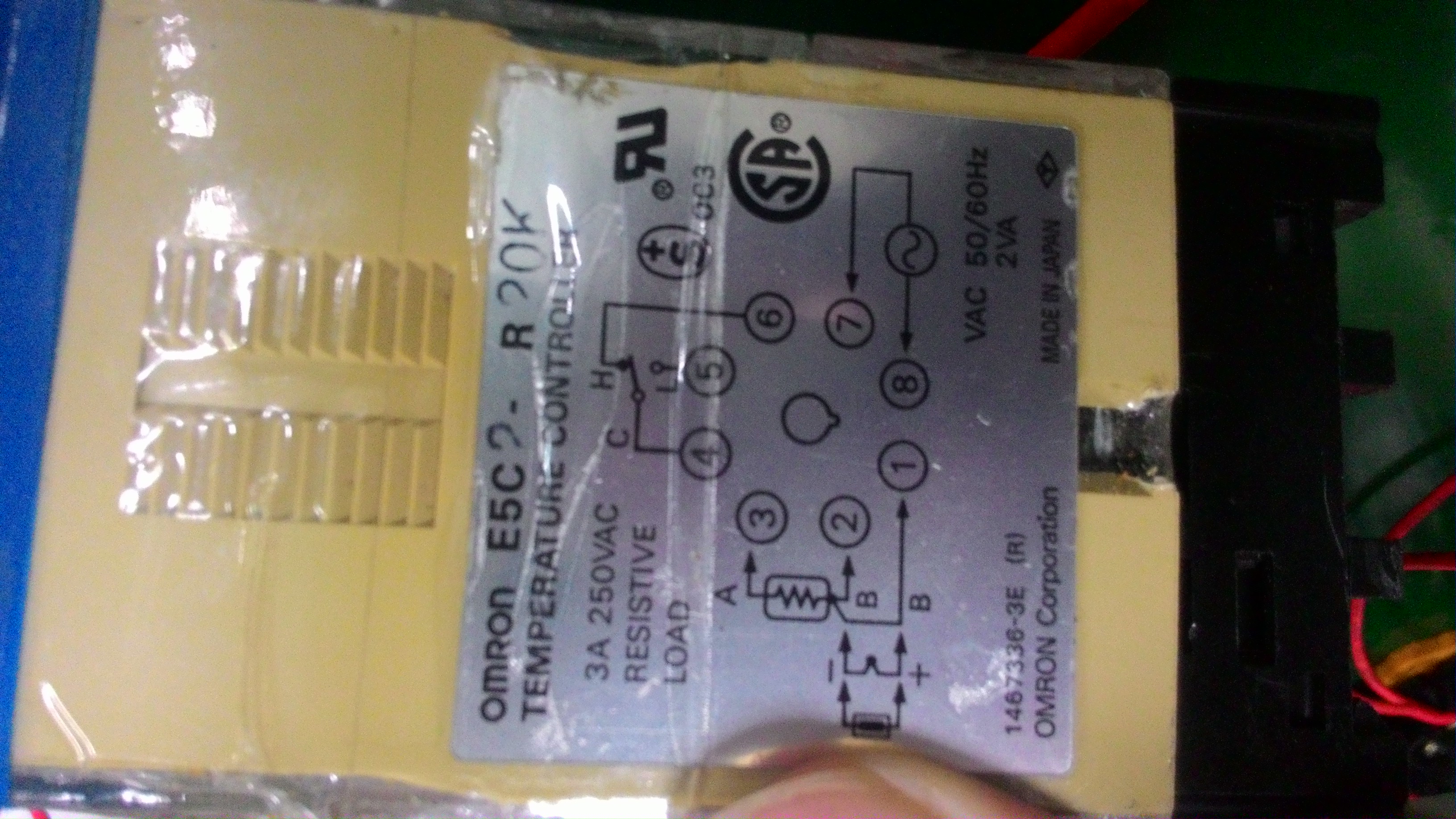
Figure 3. Thermocouple
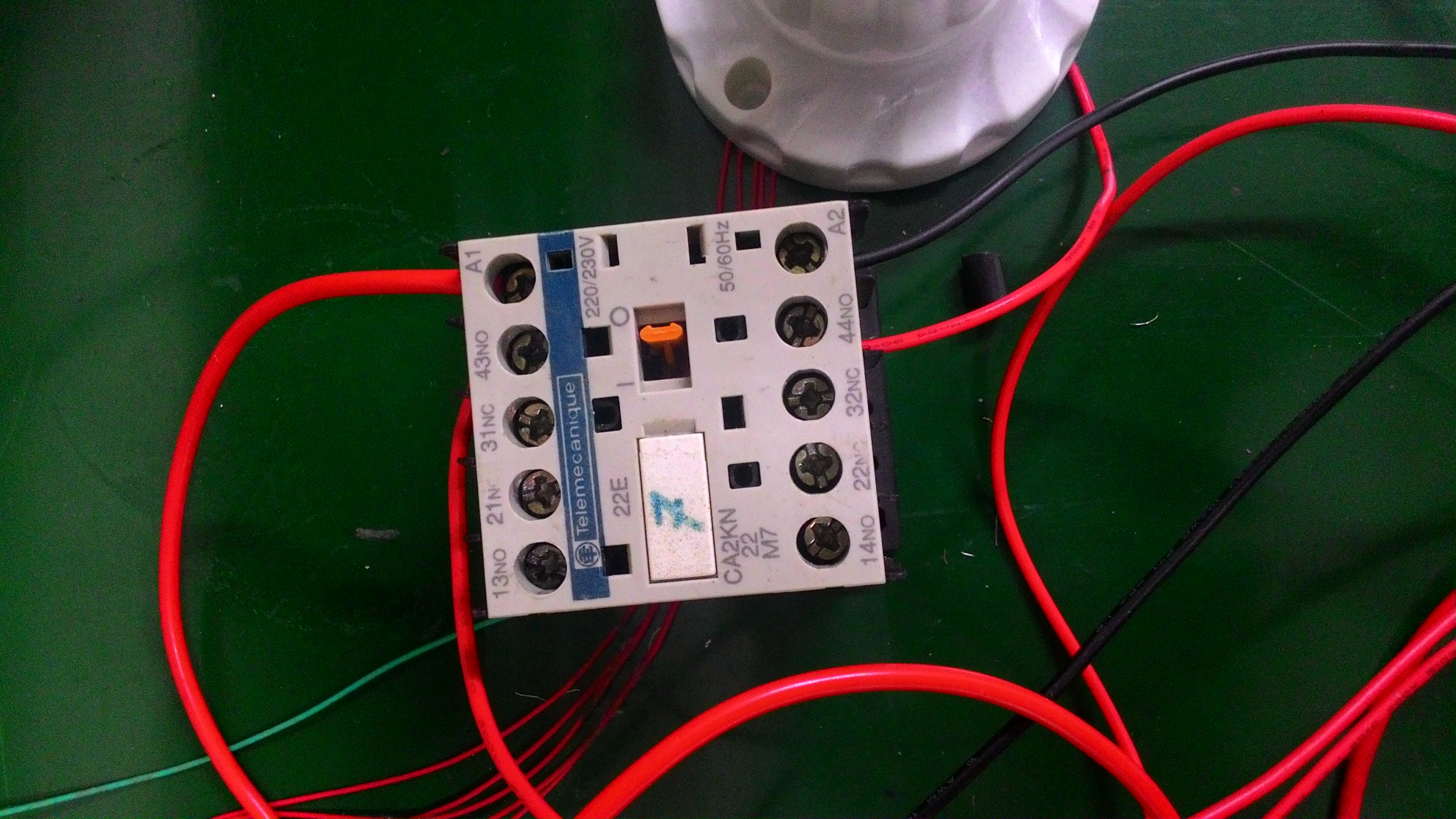
Figure 4. Contractor
3. Running the Experiment
Since it’s a practice we only connect the wires based on Figure 1, it’s not surprising that Figure 5 seems unpleasing to the eye. This will immediately be disassembled afterwards since the other devices will be use for other projects. It’ll be best to refer to this video first because it might be difficult to understand this writing if we don’t have experience in automation.
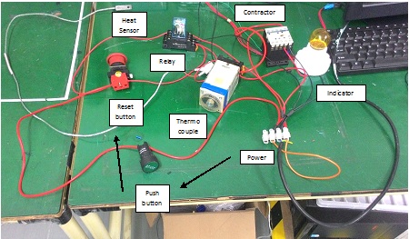
Figure 5. Experiment
In Figure 6, just pushing the push button once the light will turn and remain on. It’s because the relay is also connected to the power supply and is in connected position to the thermocouple. As of Figure 1 explanation the relay locks the current.
Then we tried heating the heat sensor using a solder in Figure 6. After while the lights goes out which proves our statement/explanation of Figure 4 (current won’t flow to bulb when heated to 100o C in this experiment). In Figure 7 the solder was released which lets the heat sensor to cool down and turned the light again. Figure 1 is the ladder diagram for the actual circuit, in Figure 8 is the simulation of what happen to the actual circuit which includes the heat sensor in the ladder diagram.
a. The heater turns on when the button is pushed heating the sensor.
b. We assumed that it takes 2 seconds to heat it up.
c. After 2 seconds (assumed reached targeted temperature) activates the sensor and will cut the line.
d. The heater will turn off.
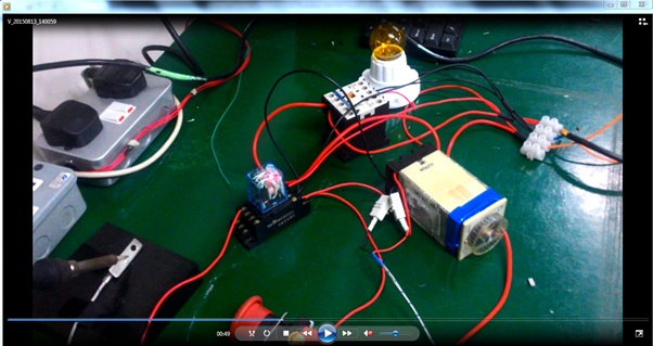
Figure 6. Affect in heating heat sensor
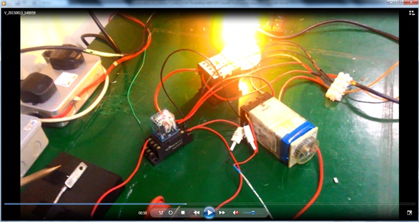
Figure 7. When heat sensor cools down
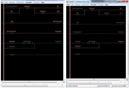
Figure 8. Simulation
4. Conclusion
Above is only simulation of a chamber room not real experiment. While the chamber work like the Air Conditioner (AC), Iron, or oven which controls the surrounding temperature this one is only to simulate the use of thermocouple where the heat sensor is manually heated up with a solder, even the relay only functions to keep the circuit alive. Thus the experiment above allowed us to able to create a concept of chamber room, design the ladder diagram, and implement them through relays and thermocouple. In summary the experiment succeeded in simulating a chamber room. The light bulb is the indicator whether the temperature is below set point or above, it lights when it’s at low temperature. The heat sensor connected to thermocouple was heated using a solder and sets it to high temperature, ultimately kills the light bulb (cuts the electric current). It will turn on again when it cools down.
Comments
Post a Comment