Note
This is a collection of my undergraduate assignments that I translated to English myself in the Basic Electrical Power Engineering course. This assignment has never been published anywhere and I, as the author and copyright holder, license this assignment customized CC-BY-SA where anyone can share, copy, republish, and sell on condition to state my name as the author and notify that the original and open version available here.
General Electric Energy Supply Process
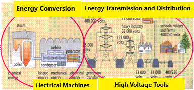
Electrical Conversion
Conversion in the field of electric power is the conversion from other energy to electrical energy. This conversion is usually used to generate electricity, producing this electricity is called a generator, in other words as a producer. Here are example sources of electrical energy: Hydroelectric Power Plant, Steam Power Plant, Nuclear Power Plant, Gas Power Plant, and Diesel Power Plant. Other generators include: Solar Power, Wind Power, Chemical Reactions, Geothermal Energy and others.
Nuclear Energy etc → Reactor Converter etc → Alternate → Transformer Step Up; Reactor Converter etc → Generate
Electric Transmission
Electric transmission is the process of sending electricity. The delivery goes through the power grid.
Step-Up Transformer → High Voltage Network → Step-Down Transformer → Medium Voltage Network → Factory
Electricity Distribution
Electricity distribution is the process of sharing electricity to consumers.
Medium Voltage Network → Step-Down Transformer → Low Voltage Network → Consumer
Basic Theories
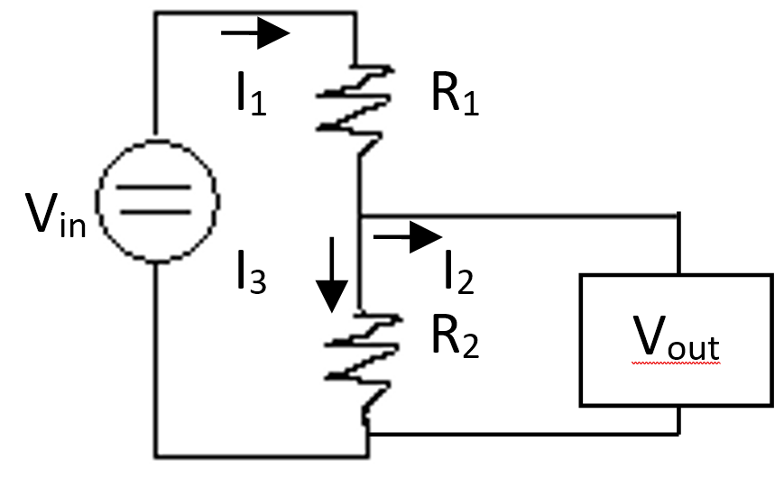
Ohm Law
Ohm law: V=IR, V = voltage (volt), I = current (ampere), R = resistance (ohm).
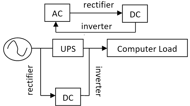
Inverter, Rectifier, UPS
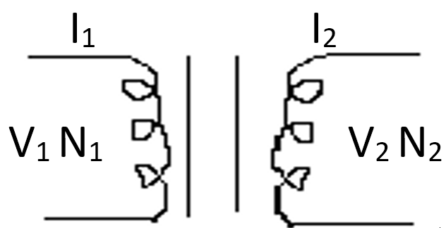
Transformator
Transformers are devices for changing the voltage. The step-down transformer lowers the voltage while the step-up transformer increases the voltage.
Magnetic Field
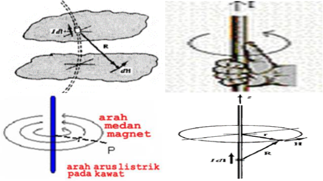
dH = (IdI x aR)/(4πR2)(A/m), H = ∮(IdI x aR)/(4πR2)
I = current (A), dl = length, aR = vector, R = vector length.
Magnetic Field Flux
B = dΦ/ds = μH, Φ = ∮Bds
B = magnetic field flux density (weber/area), Φ=magnetic field flux (weber), ds = area (m2), H = magnetic field strength (A/m)
Direct Current Generator Working Principle
The working principle of a direct current generator is based on Faraday's law: e = -N dΦ/dt
Where, N: number of turns, Φ: magnetic flux, e: induced voltage, emf (electromotive force).
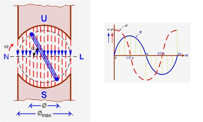
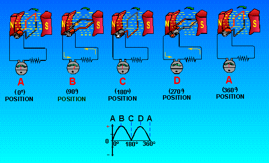
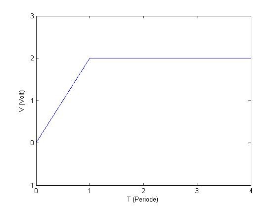
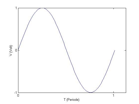
The commutator functions as a switch. The commutator is in the form of a split ring attached to the end of the anchor. When the anchor rotates, the ring will rotate. When the coil has rotated half a turn, the brush will close the ring gap so that the voltage becomes zero. Because the ring continues to rotate, the gap will open again and create tension again. If the voltage period is the same as the ring rotation period, the voltage that arises is the full wave direct current voltage.
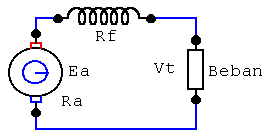
Types of Direct Current Generators Viewed from its Field Winding
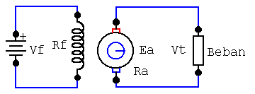
Self-Strengthening Generator
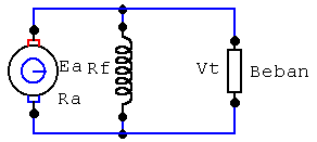
Compound
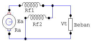
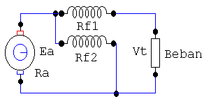
Some Exercises
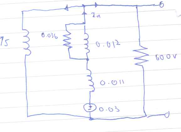
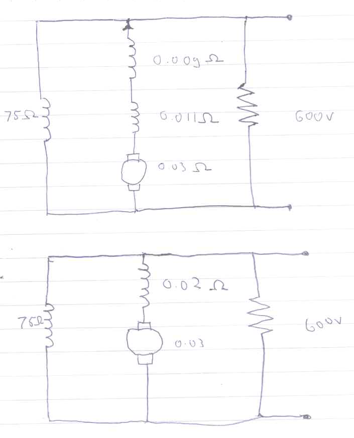
Ish = 600V/75Ω = 8A, I = 300000W/600V = 500A, Ia = Ish+I = 8A+500A = 508A
∆Vtotal = ∆V+∆Va = Ia R+Ia Ra = Ia (R+Ra) = 508A(0.03Ω+0.02Ω) = 25.4V
emfV = V+∆Vtotal = 600V+20.4V = 625.4V
emfP = (emfV)(Ia) = (625.4V)(508A) = 317703.2W
2. Transformer 1ɸ is given a 50 Hz supply step down 2200 V → 250 V with an area of 36 cm2 and a flux density of 6 wb/m2, look for the primary and secondary windings.
Known:
f = 50 Hz
E1 = 2200 V
E2 = 250 V
A = 0.0036 m2
Bm = 6 wb/m2
Asked:
N1 and N2
Answer
Φm = (Bm)(A)=(6 wb/m2)(0.0036 m2) = 0.0216 wb
E = (4.44)(f)(N)(Φm) = (4.44)(f)(N)(Bm)(A)
Primary Winding = E1/((4.44)(f)(Φm)) = 2200/((4.44)(50 Hz)(0.0216 wb)) = 458.79
Secondary Winding = E2/((4.44)(f)(Φm)) = 250/((4.44)(50 Hz)(0.0216 wb)) = 52.135
3. The power of the transformer 1ɸ is 25 KVI, the primary winding is 500, the secondary winding is 50, the primary winding is connected to a voltage of 3000 V with a frequency of 50 Hz. Find the load currents in the primary and secondary winding, secondary emf and maximum flux. (ignore the drop voltage)
Known
P = 25 VI
N1 = 500
N2 = 50
E1 = 3000 V
f = 50 Hz
Asked
I1, I2, E2 and Φm
Answer
E = (4.44)(f)(N)(Φm) = (4.44)(f)(N)(Bm)(A)
Φm = (4.44)(f)(N1)/E1 = (4.44)(50 Hz)(500)/(3000 V) = 37 wb
E2/E1 = (4.44)(f)(N2)(Φm)/(4.44)(f)(N1)(Φm) = N2/N1
E2=N2/N1 E1 = 500/50 3000 V = 30000V
P=(V)(I)
I1 = P/E1 = (25 W)/(3000 V) = 8.3mA
I2 = P/E2 = (25 W)/(30000 V) = 0.83mA
Mirror
- https://www.publish0x.com/fajar-purnama-academics/my-undergraduate-electrical-power-engineering-assignment-col-xerrpjq?a=4oeEw0Yb0B&tid=blogger
- https://0fajarpurnama0.github.io/bachelor/2020/07/02/my-undergraduate-electrical-power-engineering-assignment-collection
- https://0fajarpurnama0.medium.com/my-undergraduate-electrical-power-engineering-assignment-collection-6d01e0f78a5f
- https://hicc.cs.kumamoto-u.ac.jp/~fajar/bachelor/my-undergraduate-electrical-power-engineering-assignment-collection
- https://blurt.buzz/@fajar.purnama/my-undergraduate-electrical-power-engineering-assignment-collection?referral=fajar.purnama
- https://0darkking0.blogspot.com/2020/12/my-undergraduate-electrical-power.html
- https://stemgeeks.net/technology/@fajar.purnama/my-undergraduate-electrical-power-engineering-assignment-collection?ref=fajar.purnama
- https://0fajarpurnama0.cloudaccess.host/index.php/9-fajar-purnama-academics/167-my-undergraduate-electrical-power-engineering-assignment-collection
- https://steemit.com/technology/@fajar.purnama/my-undergraduate-electrical-power-engineering-assignment-collection?r=fajar.purnama
- http://0fajarpurnama0.weebly.com/blog/my-undergraduate-electrical-power-engineering-assignment-collection
- https://0fajarpurnama0.wixsite.com/0fajarpurnama0/post/my-undergraduate-electrical-power-engineering-assignment-collection
- https://read.cash/@FajarPurnama/my-undergraduate-electrical-power-engineering-assignment-collection-0e040885
- https://www.uptrennd.com/post-detail/my-undergraduate-electrical-power-engineering-assignment-collection~ODQxOTAx
My Undergraduate Electrical Power Engineering Assignment Collection >>>>> Download Now
ReplyDelete>>>>> Download Full
My Undergraduate Electrical Power Engineering Assignment Collection >>>>> Download LINK
>>>>> Download Now
My Undergraduate Electrical Power Engineering Assignment Collection >>>>> Download Full
>>>>> Download LINK JV