Note
Previously, this paper had the aim of fulfilling the requirements to take part in the 2013 UNUD MawaPres (Outstanding Student) where this paper was the second version of the selection at the University level which was different from first version where the first version only hangs the modem on the pan while the second version makes bazooka parabolic pan product where there is a place to put the modem and I translated the original Indonesian to English myself. The story of why I chose this topic because there was no smartphone before and still used a modem (modulator demodulator) for Internet connection. In the past, I was often invited to play online video games like DOTA (Defense of the Ancient) but had problems with Internet connection stability (not Internet connection speed). An easy way that I have come across to improve the quality of the modem signal is to use wajanbolic (parabolic pan) which I often tinker with and ideas arise about why not just write a paper on this. This paper has never been published anywhere and I, as the author and copyright holder, license this paper customized CC-BY-SA where anyone can share, copy, republish, and sell on condition to state my name as the author and notify that the original and open version available here.
Summary
The issue of a homebrew antenna made from a parabolic frying pan, a cylinder box and aluminium foil that could increase the gain of a modem (increase in signal strength) had been wide spread throughout the citizen. In Indonesia we called it wajanbolic, in English it is a homebrew parabolic antenna. But there hasn’t much people who knew the exact number of the gain and theorically how it could increase the signal strength of a modem. In this paper will be discussed the exact number of the gain and why it could increase modem’s signal strength. The advantage of this paper is the benefit for people from any class (especially low class) because they could make this device easily and quickly with cheap materials and easy to grasp.
The materials that were used to make this device for this paper are a frying pan with a diameter of 30 cm and a depth of 10 cm as a parabolic reflector, a cylinder box with a diamter of 10.8 cm and a length of 26.6 cm as the feeder (feed antenna). Above the focus point (5.626 cm) is covered with aluminium foil. The modem is place 1/3 the length that was covered in aluminium foil from the top. The making of this device was based on front feed parabolic antenna.
The result of this experiment was very satisfying. The gain of this device from the experiment is around 8.67 dB (how much the signal strength of the modem increase). Even in theory it was calculated to be 11.764 dB. That was the ideal gain but there are other factor that might caused a different result from theorical calculation. Overall it was very satisfying that it could have a gain of 8.67 dB made from cheap materials, easily and quickly made. This paper could be use for further research, maybe with diferrent device (other than modem), making this device with different materials or other things.
Chapter 1 Introduction
1.1 Background
Wajanbolic (parabolic pan) is a tool that can strengthen the signal strength received by the modem. This parabolic pan uses the concept of a parabolic antenna. The gain of a parabolic antenna depends on the antenna diameter, signal frequency and radiation pattern.
This issue has been circulating in many circles in the community, especially young people who have taken advantage of this creative idea, making their own parabolic pan from used or simple materials. Therefore this parabolic pan is often included in the category of homebrew antennas (homemade antennas for home use). In Indonesia, the basic material for making this parabolic pan is a frying pan which costs around Rp. 30000. Other materials are a paralon pipe or cylinder shaped box, a usb extender, and aluminum foil. Other tools such as scissors, tape, cutter, and others to help the process of making bolic pans. All tools and materials except the modem do not total up to Rp. 200000. To make this tool, used goods can be used, otherwise there is no need for expenses and is cost effective.
Specifically, many don't know how much signal amplification occurs and it's not 100% guaranteed that this parabolic pan can amplify the signal significantly. According to the parabolic antenna theory, the gain will be greater the larger the diameter, the higher the frequency and the more directional (narrow, efficient) radiation pattern.
Therefore, this research will examine the signal gain that occurs in the modem when using wajanbolic by linking the parabolic antenna theory.
1.2 Problem
- Are there signal gains if the modem is assisted by parabolic pan?
- How much signal gains are there?
1.3 Objective
Investigate the influence of modem signal strength using wajanbolic.
1.4 Benefit
- Get detailed information and calculations about the signal gain on the modem using parabolic pan.
- Parabolic pan is no longer an issue, but as valid information because in this study there is a theory that supports it and has been verified.
- People in any society can make parabolic pan by reading this research because the material is relatively cheap, easy to obtain with simple manufacturing steps and requires a short time.
1.5 Scope and Limitation
- The only signal amplification observed is the modem.
- The only materials used in parabolic pan are iron and aluminum (did not examine other materials).
- Parabolic pan placement is placed where there is the greatest signal amplification (does not determine elevation angle, azimuth, and does not determine the position of the BTS (Base Transmission Station)).
- Scanning for 3G (3rd Generation) networks.
- Researching the extent of signal strength obtained by the modem (does not examine data rates, and other service quality).
Chapter 2 Literature Review
The contents of chapter 2 are the same as the contents of chapter 2 in version 1 with the following additional sections:
2.10 Feed Antenna
Feed antennas usually operate at 0.6 λ - 0.75 λ. The picture is as follows:
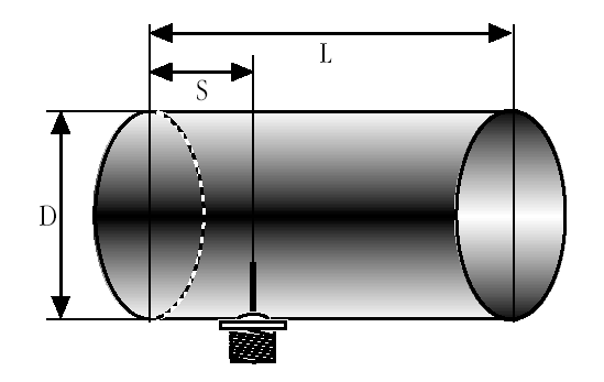
The minimum antenna diameter is 0.6 λ and the maximum is 0.75 λ. The minimum length of the can is stated by the following formula (Purbo, 2011):
L = 0.75λ / √1-(λ/1.706D)
Where:
λ = wavelength (cm) = 15.385 cm
D = diamter feeder (cm) = 10.8 cm
The wireless transmitter is put on S = 1/3 L
Chapter 3 Research Methods
3.1 Place and time of research
The research was conducted at the researcher's house, at Jln. Kusuma Bangsa 5, Denpasar, Bali. Research time on Sunday - Tuesday, March 10 - 12 2013, at 10:00 - 10:30.
3.2 Tools and Materials
Following are the tools used for research:
- Modem: Huawei E1552
- USB Extender: 3 meter
- Computer: Windows 7 Ultimate 32 bit, Intel(R) Core(TM) i5 CPU 650 @ 3.20 GHz 3.33 GHz, 4.00 GB RAM, 2283 MB VGA NVIDIA GeForce 9500 GT
- Software MDMA (Mobile Data Monitoring Application): Version 10030 C
The following are the ingredients used to make parabolic pan:
- Pan: Made of iron, Diameter = 30 cm, Height (depth) = 10 cm
- Feeder (Middle cylinder): Plastic box diameter = 10.8 cm and height = 5.625 cm, Cylinder Zinc diameter = 10.8 cm and height = 20.969
- Aluminum paper
- Tape
- Double tape
3.3 Method of Research
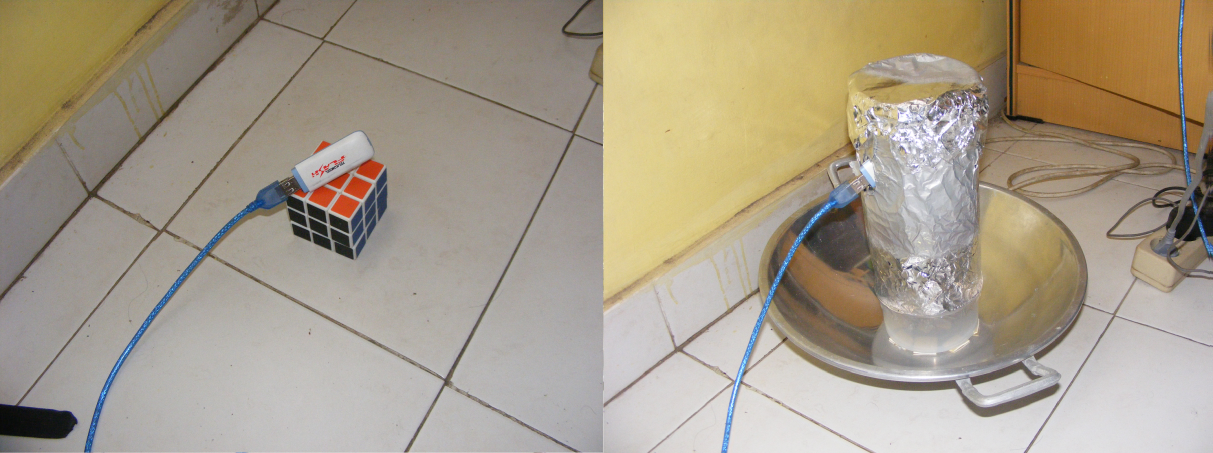
3.3.1 Parabolic Pan Making
- Prepare tools and materials.
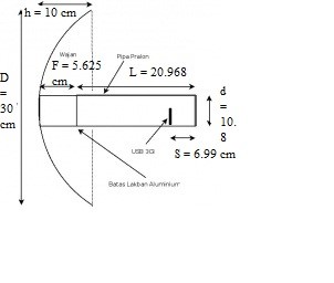
- Measure the focal point of the pan using the formula 2.3: F = D2/16h where D = diameter pan, h = parabolic pan depth, then F = 302/16(10) cm = 5.625 cm
- Make a feeder, what you must know is the 3G network frequency, namely 1950 MHz for the uplink and 2150 for the downlink, which is pegged to the uplink frequency, namely 1950 MHz.
- Measure the wavelength using the formula: λ = c/f, where c = speed of light = 3x10⁸ m/s, f = frequency (Hz), where λ = 3x10⁷m/s / 1950000000 Hz = 0.15385m = 15.385cm
- Then the feeder diameter must be minimal 0.6 λ= 9.231 cm and maximum 0.75 λ = 11.538 cm. In this research was made 10.8 cm.
- Determine the length of the feeder (minimum) with the formula L = 0.75λ / √1-(λ/1.706D) where λ = wavelength (cm) = 15.385 cm, D = feeder diameter (cm) = 10.8 cm, L = ((0.75)(15.385))/√(1-(15.385/((1.706)(10.8))))cm = 20.969cm
- Total required cylinder length = focal point distance + feeder length = 5.625 cm + 20.969 cm = 27.959 cm. 5.626 cm plastic box and 20.969 cm wrapped in aluminum.
- Modem is put on S = 1/3 Lf from above = 6.99 cm.
- Then the design becomes Figure 3.1.
- At length L = 20.968 cm wrapped with aluminum using tape and positioned on top. At length S = 6.99 cm perforated for the inclusion of the modem. Insert the cylinder into the pan using a double tap.
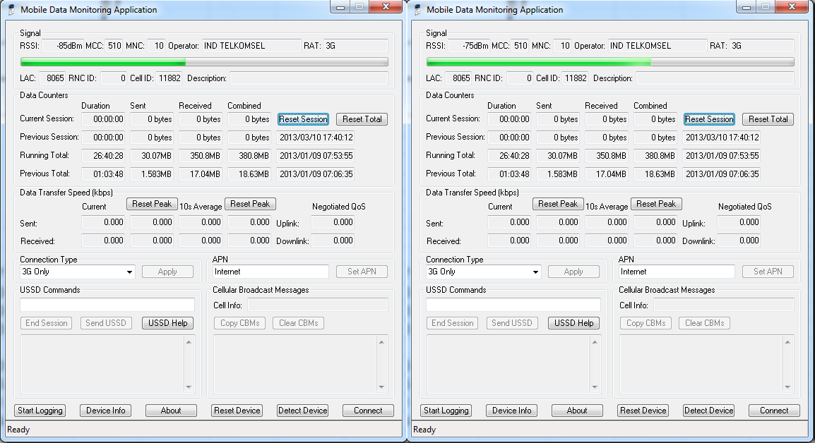
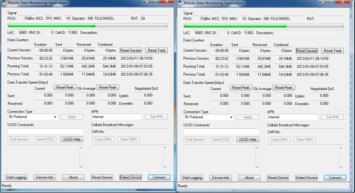
3.3.2 Signal Strength Measurement
Measurements are made on the placement of the modem with parabolic pan where the greatest signal amplification occurs. After that, the difference in the signal strength of the modem without parabolic pan and with parabolic pan is measured. The signal strength value was seen with the MDMA (Mobile Data Monitoring Application) software.
%20dan%20dengan%20wajanbolic%20(kanan).png)
3.4 Data Processing
Research data on day 1:
%20dan%20dengan%20wajanbolic%20(kanan)%201.png)
Research data on day 2:
%20dan%20dengan%20wajanbolic%20(kanan)%202.png)
Research data on day 3:
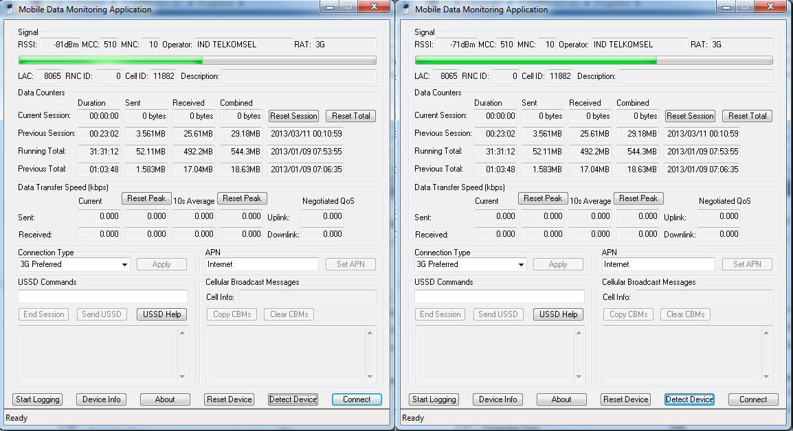%20dan%20dengan%20wajanbolic%20(kanan)%203.png)
Chapter 4 Discussion
4.1 Signal Booster Calculations
Calculation of gain is done by differentiating signal strength without wajanbolic and wajanbolic. Example of calculation on the first data:
It is known that the signal strength received on the modem is -85 dBm. After installing wajanbolic, the signal strength received on the modem becomes -75 dBm. Then the reinforcement is (-85dBm) – (-75dBm) = 10 dB.
The next calculation can be seen in the following table:
| Data | Without Parabolic Pan | With Parabolic Pan | Amplification |
|---|---|---|---|
| 1 | -85 dBm | -75 dBm | 10 dB |
| 2 | -79 dBm | -73 dBm | 6 dB |
| 3 | -81 dBm | -71 dBm | 10 dB |
| Average | 8.67 dB |
4.2 Comparison of Research Results with Theory
Based on the formula:
Gmax dB = 10log10eff(πD/λ)2
The efficiency of the front feed type dish antenna is 0.4 (Purbo, 2011). So in theory the gain is:
Gmax dB = 10log10 0.4((3.14)(0.3 m)/(0.15385 m))2 = 11.764 dB
The percentage of error is calculated by a formula:
%Deviation = |(Theory-Result)/Theory|
Then:
%Deviation = |(11.764-8.67)/11.764| = 26.3%
| Theory | Result | %Deviation |
|---|---|---|
| 11.764 dB | 8.67 dB | 26.3% |
The comparison of results with theory is not large. However an increase of 8.67 dB is large and satisfying. So that this tool is feasible to use.
4.3 Estimating the Causes of the Deviation of Results with Theory
- The research was conducted in a closed room.
- Does not perform the calculation of the evaluation angle and azimuth.
- The making of tools is imperfect (using used materials, not 100% neat, etc.).
Chapter 5 Closing
5.1 Conclusion
From the research results, it can be concluded that using parabolic pan can strengthen the signal strength received by the modem. The gain obtained was 8.67 dB. Although not as big as the theoretical calculation of 11,674 dB, the gain of 8.67 dB is a big and satisfactory gain. The advantage of this tool is that the tools and materials have a low price (nominal value) and are widely available in the market, making it easy to obtain. Although the materials used are cheap, the benefits of using this tool are great. For consumers whose neighborhoods get weak signals, this tool can help. Besides that, making this tool is easy and requires a relatively short time.
5.2 Future Work
It is recommended that the results of this writing be disseminated so that they can be used by the community, especially those with weak signal quality. It is also suggested that it can be used as further research by doing it in a blank zone (poor signal quality area), using a transmitter other than a modem (recommended at a different frequency), in more detail by taking into account the position of the BTS (Base Transmission Station) and calculating the elevation angle. and azimuth shooting signal, using different materials (maybe higher quality so the tool is more perfect), scanning on a different network (open 3G) or other things.
Bibliography
- Bevelacqua, P. 2011. http://www.antenna-theory.com access 12 March 2013.
- Bevelacqua, P. 2011 http://www.antenna-theory.com/antennas/reflectors/dish.php access 12 March 2013.
- Bevelacqua, P. 2011. http://www.antenna-theory.com/basics/frequency.html access 12 March 2013.
- Bevelacqua, P. 2011. http://www.antenna-theory.com/basics/radPattern.html access 12 March 2013.
- Confusion. 2010. http://pigeonsandplanes.com/2010/12/thoughts-on-netneutrality access 12 March 2013
- Edminister, J. 1979. Electromagnetics. New York : McGraw-Hill, Inc.
- Purbo, O. 2011. http://opensource.telkomspeedy.com/wiki/index.php/Wajanbolic_%26_Bazooka_3G access 10 March 20.1
- Stallings, W. 2001. Komunikasi Data dan Komputer. Jakarta : Salemba Teknika
- Suya, Y. 2009. Seri Bahan Persiapan Olimpiade Fisika Getaran dan Gelombang. Tangerang : PT Kandel
- Tomasi, W. 2001. Advanced Electronic Communications Systems. New Jersey : Prentice Hall International, Inc.
Mirror
- https://www.publish0x.com/fajar-purnama-academics/3g-network-modem-signal-amplification-testing-with-parabolic-xlloeyx?a=4oeEw0Yb0B&tid=blogger
- https://0fajarpurnama0.github.io/bachelor/2020/11/21/3g-network-modem-signal-amplification-testing-with-parabolic-pan
- https://0fajarpurnama0.medium.com/3g-network-modem-signal-amplification-testing-with-parabolic-pan-56029ed055da
- https://hicc.cs.kumamoto-u.ac.jp/~fajar/bachelor/3g-network-modem-signal-amplification-testing-with-parabolic-pan
- https://blurt.buzz/blurtech/@fajar.purnama/3g-network-modem-signal-amplification-testing-with-parabolic-pan?referral=fajar.purnama
- https://0darkking0.blogspot.com/2020/11/3g-network-modem-signal-amplification.html
- https://hive.blog/technology/@fajar.purnama/3g-network-modem-signal-amplification-testing-with-parabolic-pan?ref=fajar.purnama
- https://0fajarpurnama0.cloudaccess.host/index.php/9-fajar-purnama-academics/111-3g-network-modem-signal-amplification-testing-with-parabolic-pan
- https://steemit.com/technology/@fajar.purnama/3g-network-modem-signal-amplification-testing-with-parabolic-pan?r=fajar.purnama
- http://0fajarpurnama0.weebly.com/blog/3g-network-modem-signal-amplification-testing-with-parabolic-pan
- https://0fajarpurnama0.wixsite.com/0fajarpurnama0/post/3g-network-modem-signal-amplification-testing-with-parabolic-pan
- https://read.cash/@FajarPurnama/3g-network-modem-signal-amplification-testing-with-parabolic-pan-46797b6e
- https://www.uptrennd.com/post-detail/3g-network-modem-signal-amplification-testing-with-parabolic-pan~ODE1MjMy
Comments
Post a Comment