Note
Previously, this is my paper that I translated to English that had the aim of fulfilling the requirements to take part in the MawaPres (Outstanding Student) UNUD 2013 where this paper was the first version for the selection at the Faculty level. The story of why I chose this topic because there was no smartphone before and still using a modem (modulator demodulator) for Internet connection. In the past, I was often invited to play online video games DOTA (Defense of the Ancient) but had problems with Internet connection stability (not Internet connection speed). An easy way that I have come across to improve the quality of the modem signal is to use parabolic pan which I often tinker with and ideas arise about why not just write a paper on this. This paper has never been published anywhere and I as the author and copyright holder, license this paper customized CC-BY-SA where anyone can share, copy, republish, and sell on condition to state my name as the original author and notify that the original and open version available here.
Summary
In this global era people use modem to connect to the internet, whether it is for browsing the web, looking for pictures, watching videos online, downloading or uploading file, playing game online, opening social network and many other things. Still there are problems faced by users. One of them is the minimum signal strength received by the modem. With minimum signal strength the ability to connect to The Internet is minimal as well. The factors that are causing this are the range of the tower and the modem, and the environment. There are issues spread on The Internet that using parabolic steel can boost the modem’s performance (increasing the signal strength). Other factors are traffic in the virtual network, hacking that could cause problems in the network, network problem by the provider and many others that are not said here.
Before discussing analysis, there are theories that must be absorbed. Modem stands for modulator – demodulator. From those two words the function of modem can be define as an electronic device that modulate and demodulate a signal. Information is stored in signal, where signal here is electromagnetic wave. The modem modulates the signal and sends it. Modulation is a process of combining the signal with other signal with a higher frequency, with the purpose for a possible long range transmission. The modem also demodulates received signals.
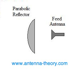
Parabolic steel is said to be able to increase the signal strength. The concept is adapted from parabolic antenna. Parabolic antenna consists of one feed antenna and parabolic reflector. The antenna works by reflecting the electromagnetic wave radiated by the feed antenna. Why it could increase the strength signal is because a feed antenna that radiates an electromagnetic wave in all direction is reflected by the parabolic dish, concentrated into one direction. It applies the same for receiving signals.
The result of the experiment is parabolic steel is able to increase the signal strength. Using the defined equation a theorist value is calculated. The theorist value of the maximum increase in signal strength for parabolic steel with a diameter of 25 cm and 32 cm are 6.42 dB – 16.07 dB. The results for the experiment are 10 dB increased for parabolic steel with a diameter 25 cm and 14 dB increase for parabolic steel with a diameter 32 cm. Those values match the theory.
Chapter 1 Introduction
1.1 Background
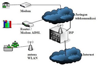
In this global era, almost everyone cannot be separated from the internet. Internet was originally a want or additional need, now it has become a human need. In ancient times we needed cables to connect to the internet. The disadvantage of using a cable is that it cannot or is difficult to carry anywhere. However, technology is getting more advanced, with the human desire to have without feeling satisfied, technology is made so that we can access the internet from anywhere. Namely access without using cables or called wireless (wireless). A wireless device for accessing the internet that is generally used by the general public is a modem.
With a modem that is about as small as an eraser rod, the modem can be taken anywhere and nowadays it can be used to access the internet almost anywhere. The more time it takes to have this tool the cheaper it is. Now almost all have modems up to children.
However, there are many problems using this modem. One of the problems is the signal strength that the modem catches. If the signal that is caught is small, then the ability to access the internet will decrease. The factors faced by the general public that cause low signal reception are the area of use and the environment. This problem will be explained further in the next chapter.
Other problems are traffic problems, equipment crashes, provider problems, hacking problems and bandwidth stealing issues will not be discussed here. Traffic problems and providers generally cannot be handled by the general public. The problem of hacking and stealing is somewhat complicated for the general public to understand.
1.2 Objective
- Provide a solution to the small signal strength received by readers with a more efficient and easy expenditure.
- Readers can develop signal capture techniques by reading this paper.
1.3 Tools and Materials
- Computer or laptop.
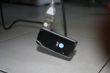
- AT&T modem with Telkomsel card. (Other modems can be used)
- AT&T Watcher software or other software that can read signal strength and display signal strength values in the form of numbers.
- USB (male-female) Connector cable.
- Parabola made of iron, aluminum or similar.
1.4 Benefit
- Readers can understand about modems and signal strength in general.
- Can improve signal capture by readers independently.
- The simple tools needed for amplification needs are relatively inexpensive.
- Easy to understand procedures take less time.
Chapter 2 Literature Review
2.1 Internet
The Internet (interconnected computer networks) can be defined as a computer network without borders, using the Internet Protocol Suite (TCP/IP) standard and being a liaison between one computer user and other computer users and can connect with computers in an area to areas around the world, where The network has various kinds of information as well as internet browsing or surfing service facilities. The Internet carries a wide variety of information sources and services, such as inter-linked hypertext documents from the World Wide Web (WWW) and the infrastructure to support e-mail.
What can be done on the internet?


2.2 Modem
Modem stands for (modulator-demodulator) is a device for connecting hardware devices (usually computers) to the Internet. The modem that is carried by the community is small in size so that it can be carried anywhere (portable). Modems can transmit and receive electric waves. In brief, the modem functions can be described as follows.
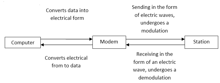
Modulation is the process of combining data signals with high frequency signals. The main purpose is so that the signal can be transmitted over long distances. If not modulated the signal will usually not arrive. The demodulation process is the separation of the two signals.
2.3 Electricity
In an atom there are three kinds of charges. Positive, negative and neutral charges. positive charge is called "proton", negative charge is called "electron" and neutral charge is called "neutron". Similar charges (++, --) repel each other, different charges (+ -) attract each other. Electricity is a charge that flows, in the salt bridge in chemistry, electricity can be generated because of the flowing electrons.
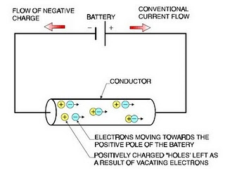
2.4 Electric Current
Current is defined as charge flowing in units of time.
I=dq/dt, dq=q2-q1, dt=t2-t1
I = Current (ampere)
q = Charge (coulomb)
t = Time (second)
To make it easy to understand the formula above, it can be said current is the amount of coulomb that flows every second. The person who contributed to the discovery of the flow was a mathematician and physicist from France, namely André-Marie Ampère.
2.5 Voltage
The voltage in electricity can be said to be the amount of energy carried by each charge. Can be analogous to the amount of pressure on flowing water.
V=dw/dq
V = voltage (volt)
W = energy (joule)
q = charge (coulomb)
For easy understanding this formula can be said the energy contained per 1 coulumb. The name volt comes from physicists from Italy Count Alessandro Giuseppe Antonio Anastasio Volta.
2.6 Power
Power is the power of electricity. Power is the work done every second. The power will be greater if the current or voltage or both are getting larger.
P=dw/dt=VI
P = power (watt)
W = energy (joule)
V = voltage (volt)
I = current (ampere)
t = time (detik)
2.7 Electromagnetic Wave
First, an electric current can produce (induce) a magnetic field. This was discovered by Oersted. Then the formula is completed by the Ampere and is known as the Ampere-Law.
Both time-varying magnetic fields can produce (induce) a time-varying electric field. This discovery by Michael Faraday and Joseph Henry became known as Faraday-Law and Henry-Law.
Third, if a time-varying magnetic field can produce (induce) a time-varying electric field, the opposite can be done. An electric current that changes with time can produce a magnetic field that changes with time.
Finally, if these two things are done continuously, there are factors that vary with time. The magnetic field becomes an electric field, becomes a magnetic field, becomes an electric field and so on. Then you can find the electric and magnetic fields in the room. This is what is called an electromagnetic wave. This was discovered by James Clerk Maxwell.
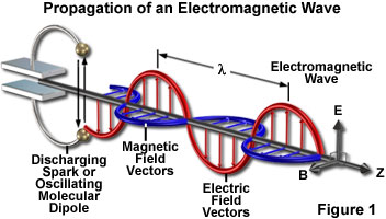
Electromagnetic Wave Characteristics:
- Can propagate in a vacuum.
- It is a transverse wave (vibration direction ^ direction of propagation), so it can experience polarization.
- Can experience reflection, refraction, interference and diffraction.
- Not deflected in an electric or magnetic field.
2.8 Antenna
In the field of electricity an antenna is a device that converts electric current into radio waves and vice versa. Radio, television, telephone, radar, and other similar devices use antennas for telecommunications. Antenna radiates electric current energy in the form of electromagnetic waves. The antenna can be both a sender and a receiver.
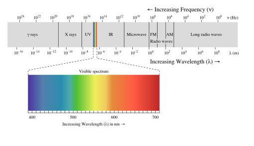
2.9 Frequency
Frequency is one of the most important concepts. Frequency is an alternating pattern represented by numbers. Heinrich Hertz said 1 Hertz = Vibration/Second, frequency is an alternating pattern in units of time.
Electromagnetic waves have different frequencies, as for the types of waves divided according to frequency. As for matters relating to frequency.
The period is the time it takes to perform an alternating pattern, the time it takes to perform a vibration T=1/f.
Waves also have length and velocity. Can be formulated v=λf.
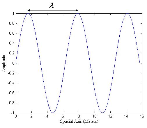
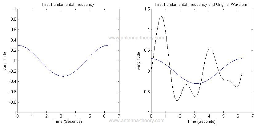
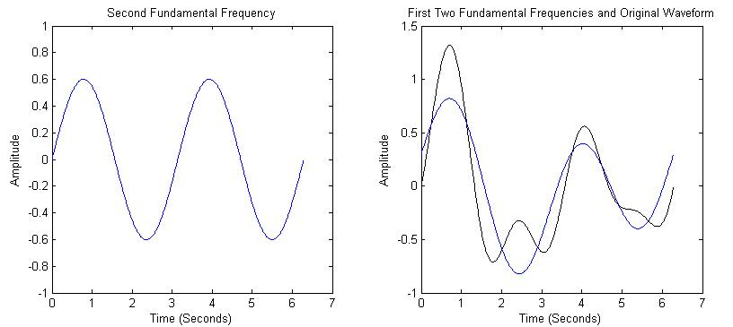
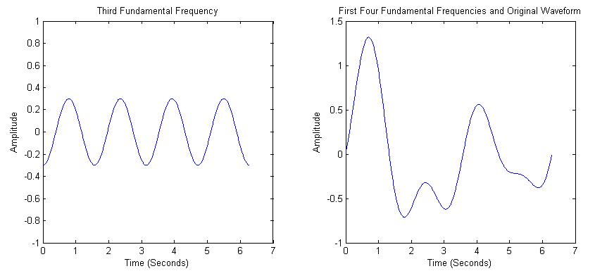
In further learning in Fourier's analysis it can be stated that any wave is the sum of sinusoidal waves with different frequencies.
It was said before that the waves have different frequencies. The electromagnetic signal as we know it today has a different frequency range.
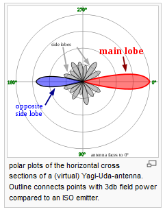
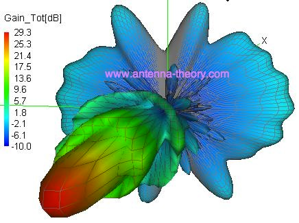
2.10 Radiation Pattern
Of the several types of antennas that we know today have different radiation patterns. The radiation pattern shows the strength of the radio waves emitted in each direction.
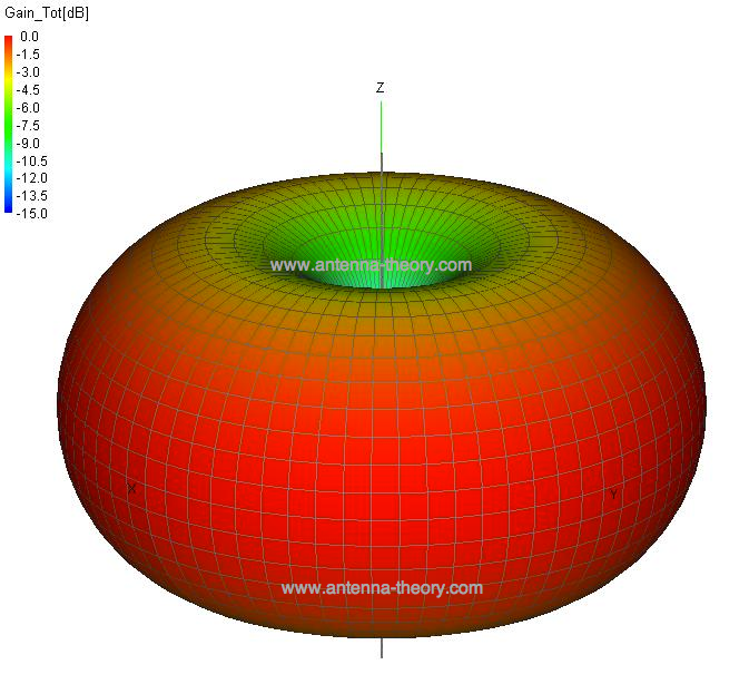
.png)
2.11 Signal Strength
The unit of signal strength is watts. Signal strength is electric power. However, the signal strength that is often used is large. The watt unit is no longer used. A commonly used unit of signal strength is dB (decibel).
PdB=10logP
P = power (watt)
For example, if the emitted power is 10 kW. Then: PdB=10log10000=40 dB
2.12 Free Space Loss
Why is there a term that can receive a strong signal, a low signal or a weak signal, or even no signal at all? One of the influencing factors is Free Space Loss. The signal strength will decrease the farther the signal propagates without a conductor (medium).
FSL = 32.5 + 20log10d + 20log10f
d = distance (km)
f = frequency (MHz)
For example, if the signal strength transmitted by the BTS is 40 dB, how many signals will the modem pick up within 150km if the FSL (free space loss) is 1 dB per km?
FSL within 200 km = (1dB)(150) = 150 dB
Signal received by modem = Radiation BTS − FSL = 40dB − 150dB = −110dB
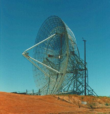
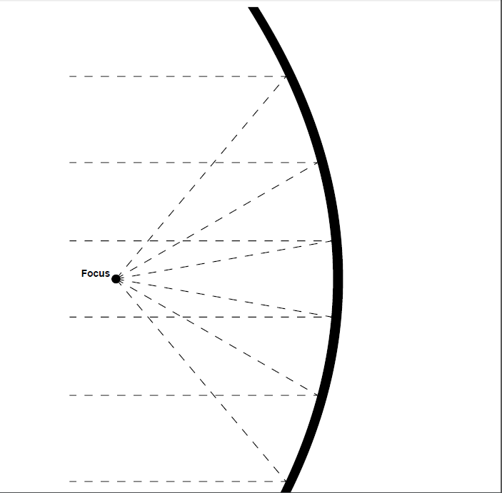
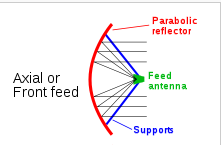
2.13 Parabolic Antenna
The working principle of a parabolic antenna is reflection, therefore it is often referred to as The Parabolic Reflector Antenna or Satellite Dish Antenna. Small antennas work at a frequency of 2 GHz - 28 GHz while large ones from 30 MHz – 300 MHz.
The basic modeling is that the feed antenna is directed against the plate.
The geometry of the parabolic antenna can be seen as follows:
x2 = 4F(F-z), |x| ≤ D/2
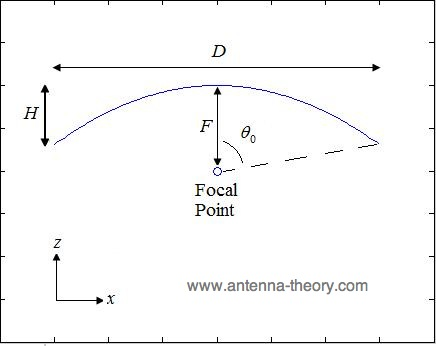
F/D = 1/4tan(θ0/2)
F = D2/16H
Where:
D: Plate Width
H: Total Height of Plate Bending
F: Focal Point
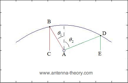
From the picture above, it is analyzed geometrically:
- All radiation emitted from the focal point will be reflected in the same direction.
- The distance traveled from the focal point to the reflector and experienced reflection is constant.
To be clearer, it can be seen from the following picture:
Types of parabolic dishes:
Chapter 3 Writing Method
3.1 Type of Data
Data in the form of the type of material used, another type of data is the signal strength number received by the modem using decibel units.
3.2 Writing Design
Writing begins with a background, namely a general description of the problem of using modems in society in general. Then written theories in the field of electrical engineering, majoring in telecommunications which the author considers important to understand this paper. The essence of writing is in the analysis and synthesis which contains data on how successful the tools made by the author are. The writing ends with conclusions and suggestions based on the experimental results.
3.3 Writing Preparation
Previous authors have attended and graduated from Basic Communication Systems, Antennas and Propagation, and Digital Communication Systems. By following the lecture, the writer has sufficient insight to write this paper. Further knowing about the issue that the signal can be amplified with a frying pan.
3.4 Data Collection Technique
Data were collected based on variations in the value of the diameter and height of the parabolic. The focal value of the parabolic is calculated using a formula, the modem signal strength in decibels can be seen in the mobile watcher software.
3.5 Data Processing Techniques
The data were processed using the comparison of each trial. The essence of processing is the number obtained by the signal strength captured by the modem before and after using the parabolic reflector.
Chapter 4 Analysis and Synthesis
4.1 Theoretical Calculations
Calculation of the ideal focal length so that waves can be reflected in 1 direction can be seen in section 2.13 Parabolic Antenna.
The maximum gain that a parabolic dish can capture can be calculated by the formula:
λ = v/f
Gmax = (4π/λ2)A = π2D2/λ2
GdB = 10logGmax
λ = Wavelength (meter)
v = Wave speed (speed of light = 3 x 10⁸ m)
f = signal frequency (Hz)
A = Parabolic dish area (square meters)
D = Parabolic dish diameter (meter)
G = Gain (watt)
Experiment using:
- Laptop ACER Intel Pentium dual-core.
- Modem AT&T with telkomsel halo card.
- USB data cable (male-female).
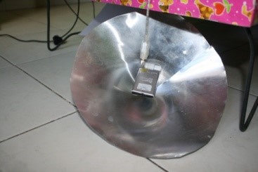
- Parabolic frying pan diameter 25 cm with height 8 cm.
- Parabolic frying pan diameter 32 cm with height 10 cm.
- Steel sheet diameter 25 with height 8 cm.
If theoretically it can be calculated:
GSM working frequency ranges between 800MHz-1900MHz in Indonesia.
The estimated wave length of 800MHz:
λ = v/f
λ = ((3)(10)8)((800)(10)6)
λ = 0.375 meter
Estimated wave length if the frequency is 1900MHz.
λ = v/f
λ = ((3)(10)8)((1900)(10)6)
λ = 0.158 meter
For pan 1 and paper iron D (diameter) of 0.25 m if the frequency is 800MHz:
Gmax = π2D2/λ2
Gmax = 3.1420.252/0.3752 = 4.39 watt
GdB = 10logGmax
GdB = 10log4.39 = 6.42 dB
For pan 1 and foil D (diameter) of 0.25 m if the frequency is 1900MHz.
Gmax = π2D2/λ2
Gmax = 3.1420.252/0.1582 = 24.71 watt
GdB = 10logGmax
GdB = 10log24.71 = 13.9 dB
For pan 2 and foil D (diameter) of 0.32 m if the frequency is 800MHz.
Gmax = π2D2/λ2
Gmax = 3.1420.322/0.3752 = 7.19 watt
GdB = 10logGmax
GdB = 10log7.19 = 8.57 dB
For pan 2 and foil D (diameter) of 0.32 m if the frequency is 1900MHz.
Gmax = π2D2/λ2
Gmax = 3.1420.322/0.1582 = 40.48 watt
GdB = 10logGmax
GdB = 10log40.48 = 16.07 dB
For pan and iron foil diameter 0.25 m, maximum Gain 6.42dB – 13.9dB.
For pan diameter diameter 0.32 m, maximum Gain 8.57dB – 16.07dB.
Calculation of the distance between the parabolic dish and the transmitter (focal length):
F = D2/16H
F = focal length
D = diameter
H = height
For pan and iron paper with a diameter of 25cm and a height of 8cm:
F = 252/(16)(8) = 4.88cm
For pan and iron paper diameter 32cm by 10cm high:
F = 322/(16)(10) = 6.4cm
For pan and iron paper diameter of 25cm the modem is placed at a height of 4.88cm and for the 32cm diameter pan the modem is placed at a height of 6.4cm.
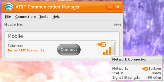
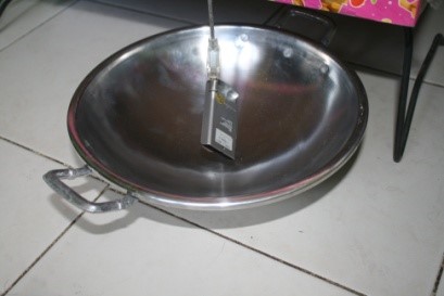
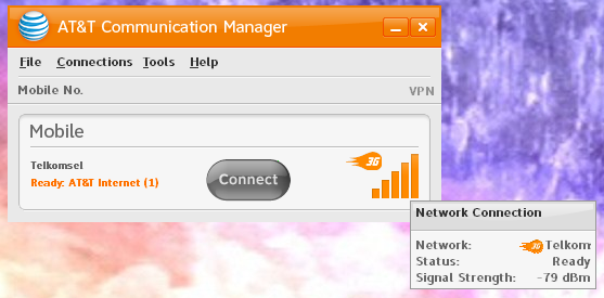
4.2 Value of Signal Strength before Using Parabolic Reflector
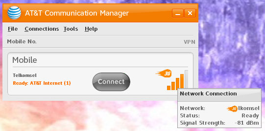
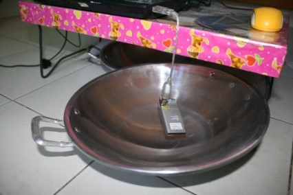
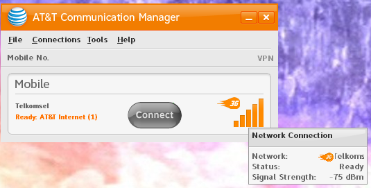
4.3 Value of Signal Strength after Using Parabolic Reflectors
4.4 Data Analysis
By using iron paper with a diameter of 25cm, there was an increase in signal strength by:
Gain = Signal strength value after - The signal strength value before
Gain = 81dBm − 89dBm = 8dB
There was an increase of 8dB.
By using a 25cm diameter parabolic pan, the signal strength increased by:
Gain = 79dBm − 89dBm = 10dB
There was an increase of 10dB.
By using a 32cm diameter parabolic pan, the signal strength increased by:
Gain = 75dBm − 89dBm = 14dB
There was an increase of 14dB.
When compared with theoretical data:
| Device | Theory | Experiment | Description |
|---|---|---|---|
| Iron sheet diameter 25cm | 6.42dB– 13.9dB | 8dB | In accordance with the theory |
| Parabolic pan diameter 25cm | 6.42dB– 13.9dB | 10dB | In accordance with the theory |
| Parabolic pan diameter 32cm | 8.57dB– 16.07dB | 14dB | In accordance with the theory |
Chapter 5 Closing
5.1 Conclusion
The experiment above adopts the concept of a parabolic antenna, especially the front feed parabolic antenna. The signal strength capture using a parabolic tool is influenced by the type of material, the diameter, frequency and wavelength of the transmitter. The types that are suitable for reflecting waves are iron, aluminum and the like. The larger the diameter of the parabola, the greater the maximum signal strength value that can be captured by the parabola (maximum gain). On the contrary, at wavelength, the wavelength the smaller the maximum gain. To reduce the wavelength by increasing the emitted signal frequency. From the experiment above, it can be concluded that the parabolic pan can improve signal strength capture.
5.2 Future Work
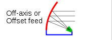
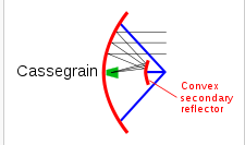
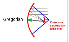
To do the experiment above or for daily needs, it is enough to buy a frying pan at a price of approximately Rp. 25,000 and a data cable (male - female). What needs to be considered is the calculation of the placement of the modem in the pan using the focal length formula. The experiment above only uses the concept of the front feed parabolic antenna. Readers can develop this using other antenna concepts, for example: offset antenna, cassegrain antenna, gregorian antenna, and others.
Bibliography
- Yohanes, Surya. Prof., Ph.D. 2009. Seri Bahan Persiapan Olimpiade Fisika Getaran dan Gelombang. Tangerang: PT Kandel
- Irwin, J. David.1993. Fourth Edition Basic Engineering Circiut Analysis. United States of America: Macmillan Publishing Company
- Wade, Paul. 1994 Chapter 4, Parabolic Dish Antennas.
- ….. 2002. List of GSM cell phone frequencies by country. http://allworldcellphones.com/gsm-frequencies-list.htm. Access 7 April 2012
- ….. 2012. Antenna (Radio). http://en.wikipedia.org/wiki/Antenna_(radio). Access 7 April 2012
- ….. 2012. Antena (Radio). http://id.wikipedia.org/wiki/Antena_(radio). Access 7 April 2012
- ….. 2009. Introduction to Antennas. http://www.antenna-theory.com/intro/main.html. Access 7 April 2012
- ….. 2009. Antenna Basics. http://www.antenna-theory.com/intro/main.html. Access 7 April 2012
- ….. 2009. Frequency. http://www.antenna-theory.com/basics/frequency.html. Access 7 April 2012
- ….. 2009. Frequency – More Advanced Concept. http://www.antenna-theory.com/basics/frequency.html. Access 7 April 2012
- ….. 2009. Radiation Pattern. http://www.antenna-theory.com/basics/radPattern.html. Access 7 April 2012
- ….. 2009. The Parabolic ReflectorAntenna (Satellite Dish). http://www.antenna-theory.com/antennas/reflectors/dish.php. Access 7 April 2012
- ….. 2009. The Parabolic ReflectorAntenna (Satellite Dish) - 2. http://www.antenna-theory.com/antennas/reflectors/dish2.php. Access 7 April 2012
- ….. 2009. The Parabolic ReflectorAntenna (Satellite Dish) - 3. http://www.antenna-theory.com/antennas/reflectors/dish3.php. Access 7 April 2012
- ….. 2012. Parabolic Antenna. http://en.wikipedia.org/wiki/Parabolic_antenna. Access 7 April 2012
- ….. 2012. Antena Parabola. http://id.wikipedia.org/wiki/Antena_parabola. Access 7 April 2012
- ….. 2000. Sifat Gelombang Elektromagnetik. http://kambing.ui.ac.id/bebas/v12/sponsor/Sponsor-Pendamping/Praweda/Fisika/0339%20Fis-3-4c.htm. Access 7 April 2012
- Sapta, Bayu Hari. 2008. Gelombang Elektro magnetic. http://aktifisika.wordpress.com/2008/11/17/gelombang-elektromagnetik. Access 7 April 2012
Mirror
- https://www.publish0x.com/fajar-purnama-academics/testing-parabolic-pans-as-a-signal-amplifier-tool-on-at-and-xejqedw?a=4oeEw0Yb0B&tid=blogger
- https://0fajarpurnama0.github.io/bachelor/2020/11/18/testing-parabolic-pans-as-a-signal-amplifier-tool-on-att-modems
- https://0fajarpurnama0.medium.com/testing-parabolic-pans-as-a-signal-amplifier-tool-on-at-t-modems-5492c0d837a4
- https://hicc.cs.kumamoto-u.ac.jp/~fajar/bachelor/testing-parabolic-pans-as-a-signal-amplifier-tool-on-att-modems
- https://blurt.buzz/blurtech/@fajar.purnama/testing-parabolic-pans-as-a-signal-amplifier-tool-on-at-and-t-modems?referral=fajar.purnama
- https://0darkking0.blogspot.com/2020/11/testing-parabolic-pans-as-signal.html
- https://hive.blog/technology/@fajar.purnama/testing-parabolic-pans-as-a-signal-amplifier-tool-on-at-and-t-modems?ref=fajar.purnama
- https://0fajarpurnama0.cloudaccess.host/index.php/9-fajar-purnama-academics/109-testing-parabolic-pans-as-a-signal-amplifier-tool-on-at-t-modems
- https://steemit.com/technology/@fajar.purnama/testing-parabolic-pans-as-a-signal-amplifier-tool-on-at-and-t-modems?r=fajar.purnama
- http://0fajarpurnama0.weebly.com/blog/testing-parabolic-pans-as-a-signal-amplifier-tool-on-att-modems
- https://0fajarpurnama0.wixsite.com/0fajarpurnama0/post/testing-parabolic-pans-as-a-signal-amplifier-tool-on-at-t-modems
- https://read.cash/@FajarPurnama/testing-parabolic-pans-as-a-signal-amplifier-tool-on-att-modems-fafc9603
- https://www.uptrennd.com/post-detail/testing-parabolic-pans-as-a-signal-amplifier-tool-on-at-t-modems~ODE0NDY1
Comments
Post a Comment